Why should you build your own slider?
A camera slider is the perfect tool to capture smooth video footage or a moving timelapse, but professional camera equipment can be quite expensive. So I decided to build my very own motorized slider from scratch. My goal was to keep the cost below $50 while delivering good enough quality for me to use the slider regularely. I started with a list of must have features:
Must have features
Timelaps capability
I would like to be able to create moving timelapses so the slider has to have a motor and a remote for the camera as well as some sort of remote for the slider itself to control the number of photos, the distance the camera moves between shots and the duration of the timelapse.
I also want to be able to create custom movement profiles using "keyframes".
Small formfactor
My fist slider was very big. As a traditional slider it is as long as the camera is able to move. This time we are going to use a very clever design I first saw on the edelkrone slider plus. Unforionately this slider costs upwards of $900. Anyways, by using two moving gantrys (one for the camera and one for the tripod mount) instead of just one, the slider can be half the size. Take a look at fig 1.1 to better understand this concept:
This video is from https://edelkrone.com/products/sliderplus (visited on 26.06.2020)
Carrying handle
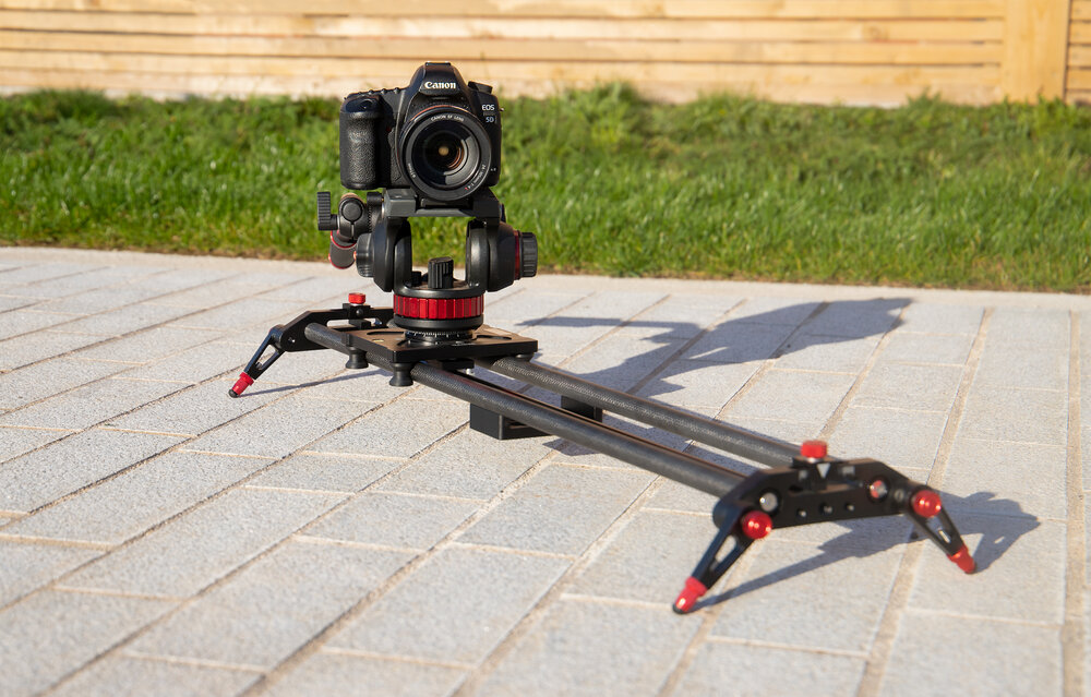
Using my first camera slider (fig 1.2) I got used to using the outer tubes as a carrying handle. I want to be able to to the same with v2 so it has to have two seperate guide rails (not one big rail).
Electronics
As I am very familiar with arduino and I think it is easier to understand for most readers than avr c I want to use an atmega328P. Since I designed my last slider, PCBs have gotten much cheaper I want to design a PCB for a more professional look. You will also be able to download the design files yourself to follow along!
Upgradeability
I would like to add a 3-axies gimbal in the future. I want the slider to be able to control the camera position during timelaps mode.
Design considerations (What is important?)
Guiderails
Since we have two moving gantrys I don't want to use round tubes as guidrails. I think it is best to use 2020 v-slot aluminuim extrusions as they are cheap and the two gantries can easily be mounted using v-slot rollers.
Sag
The number one error I have seen on other slider projects is sag. If the chosen rods are too weak the slider is unusable as the camera will not move on a straight line. However as we will be using short 2020 aluminum extrusions this is not a problem. If you use rods like I did in my first slider, make sure to calculate the sag. 12mm rods as used in most 3d printers are too weak! I used 20mmx1mm steel pipes.
Motor torque
If the torque of the chosen motor is not big enough the slider won't be able to be used at an angle. This is one of the mistakes I made last time.
Calculating the required torque
As you can see in fig. 2.1, the torque of a motor is given by T=r*F_T where r is the length of a lever connected to the motor shaft and F_T is the force applied. Combined with fig. 2.2 and 2.3 it is easy to see how to calculate the required torque \(T = r\cdot F_T=R\cdot F_A\)
F_T is specified by on the datasheet for your motor and F_A can be can be calculated using the weight of the slider including your camera G (F_G=G*9.81) and
$$F_A=\frac{\cos^{-1}(\varphi)}{F_G}$$
where phi is the max angle you would like to use your slider at.
You can see the connection between F_A,F_G and F_N in fig. 2.3. As we are using bearings on the gantry we are not taking friction into account. Instead we will use a motor with a slightly higher torque rating than calculated here. So
$$T>R*F_G.$$
Power supply
Most people alredy have a powerbank at home and I think it would be great if you could power the slider from it. As the motor requires 12V we could use a powerbank supporting usb-pd. However this will make the pcb design more complicated and not suitable for a beginner project. We will instead use a boost up converter to convert the supplied 5v to 12v. This is not perfect as these converters are not very efficient. To make sure this will work we have to do some calculations and mesurements first:
Calculating battery runtime
The capacity of a Powerbank is usually given in mAh, telling you how many milli-Amps the powerbank can supply for one hour. The secone important spec is the maximum power output (usually in amps or watts).
The converter's efficiency can usually be approximated as a constant between 75% and 95%. We will assume an efficiency of 80%. As most cheap motors don't come with a reliable datasheet we will measure how much power the motor draws under load. Please note that the measured power draw is with respect to 12V. As the powerbank will supply 5V, the motor will actually draw
How to make a motorized slider
3d design
As with most projects I started with a 3d model of the slider. You can see it in fig. 3.1. The gantry for the tripod will use v-slot rollers to move between the two extrusions. The camera gantry will ride on top of the extrusions.
Both gantries as well as the ends of the slider will be 3d printed. A link to all models can be found in the
downloads-section below.
Choosing a suitable Motor
I would like to use a nema 17 pankace stepper motor as they are cheap, readily available and easy to work with. A stepper motor can also be used to position the camera accurately for moving timelapses.
We have already seen how to calculate the required Torque. My camera weighs 480g, the slider XXXg (including the motor) and I would like to use the slider at an angle of up to 90deg. Since I also want to add a gimbal in the future lets assume a maximum weight of 1.5kg. Thus I have to choose a motor with at least 0.118Nm of torque. Unfortionately a standard nema 17 pancake motor with 0.13Nm torque is not sufficient. This is because the rated torque is the holding torque of the motor. The actual torque while moving is much lower. Thus the motor would be able to hold the slider in place but it would not be able to move it.
To circumvent this problem we'll use a 40:1 worm gear to drive the belt connecting both gantries. This might be a problem for filming as we reduce the maximum speed the camera can move at by a factor of 40, but as I mainly want to capture hyperlapses this is not a problem for me.
Furthermore we might be able to disable the motor when not moving as the worm gear should prevent any unwanted movement, saving a lot of power.
PCB design
Designing a pcb is quite boring so here is the result:
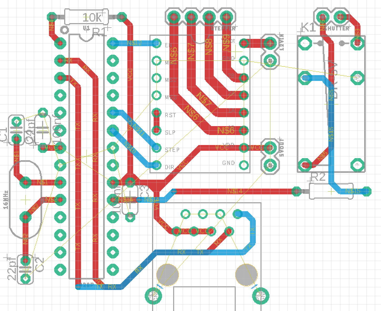
To accomodate for all the features we want the board features:
- Atmega328p (programmable with arduino)
- A4944 stepper-driver to control one stepper motor
- microswitch input for homing
- esp328 for remote control via wifi
- A relais to control the camera shutter in timelaps mode
- DC-DC converter to use a standard 5v powerbank
We'll be using an esp328 to control the slider via wifi from a phone, tablet or laptop. This also makes the slider cheaper as we don't need to build a seperate remote control. However it will be more challenging to program.
You can download the PCB-files in the download-section below.
Programming
Programming an atmega 328p is very simple. We'll use an Arduino to program the atmega and then remove it from the arduino board and plug it into our custom pcb. Programming an esp328 is a bit more complicated as we have to enter programming mode first and then use an arduino as ICSP to program the microcontroller. Take a look at this video for a how to:
Software-features:
- Different movement types :Continuous motion, acceleration, ease-in/out
- Timelaps mode
- keyframe support. Move the camera and set keyframes. The slider can then use its motor to move between keyframes, take photos etc.
- Webinterface for remote control over wifi
You can download the Code in the download-section below!
Assembly
As I have alredy assembled everything in cad all parts fit together very nicely. Here are some pictures of me assembling the new slider:
Resumee
I am very happy with how this project turned out. It improves upon my original design in almost every way. I am also very proud that this project is very easy to recreate as you can order the pcb and print all other non-standard parts, minimizing the work you have to do! It is almost like a lego set for adults. Assembling a kit where everything fits together! The features are also great and I already tested it out in Vienna. Take a look:
Downloads


Comments