


In recent years the ESP8266 has become one of my go-to choices for smart home/IoT devices or projects requiring WiFi. It is cheap (around $1.5 on Amazon)1, has WiFi, and can be programmed using the Arduino IDE, making it an easy replacement for Arduinos if we need WiFi connectivity.
This post concentrates on the technical specifications of different ESP8266 modules and the minimal circuit required to use each ESP module. It is part of a complete ESP8266 reference you can find here.
The information in this chapter is primarily taken from the datasheets of the different modules [8,9,10,11,12].
The ESP-01 and ESP-1 modules are among the cheapest options. They feature eight exposed pins (2.54mm pin header), of which only two are usable GPIO pins. The modules differ in the following way:
| Module | Flash memory | LEDs | Other |
|---|---|---|---|
| AI-Thinker ESP-01 | 512kB (blue) or 1MB (black) | Power (red), GPIO2 (green) | |
| AZ-Delivery ESP-01S | 1MB | GPIO2 (blue) | additional pull-up resistor on EN pin |
| DOIT ESP-1 (ESP82855) | 1MB | TxD (blue) |
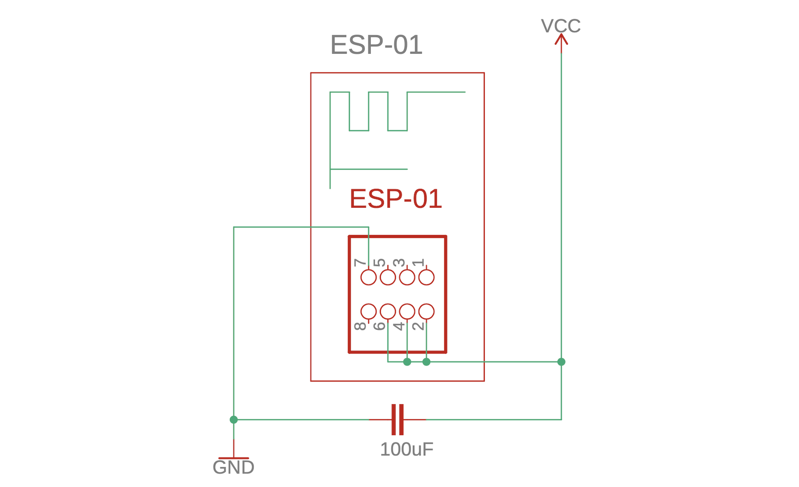
| Pin No. | Name | Description | Behavior on boot |
|---|---|---|---|
| 1 | GPIO3 (RxD) | Serial input/GPIO | pulled high |
| 2 | VCC | +3.3V, uses up to 430mA | pulled high |
| 3 | GPIO0 | low on boot to enter programming mode, high or floating for normal boot | |
| 4 | RESET | low to reset, see Fig. 2.2 | |
| 5 | GPIO2 (TxD1) | normal gpio | serial output, not allowed to be low |
| 6 | CHIP_EN | high to enable chip, low to shut down | |
| 7 | GND | ground | |
| 8 | GPIO1 (TxD) | serial output or normal gpio | serial output, not allowed to be low |
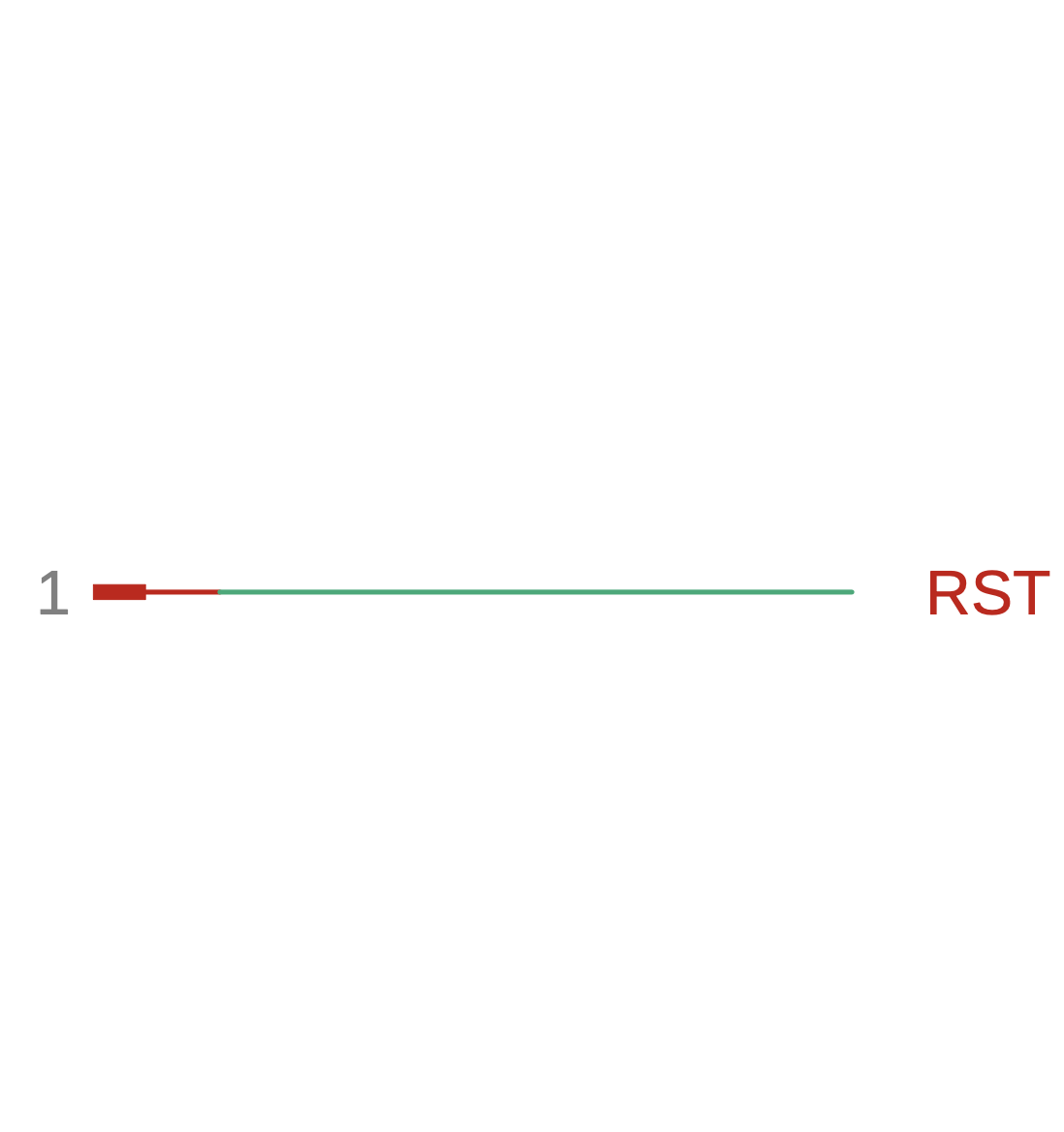
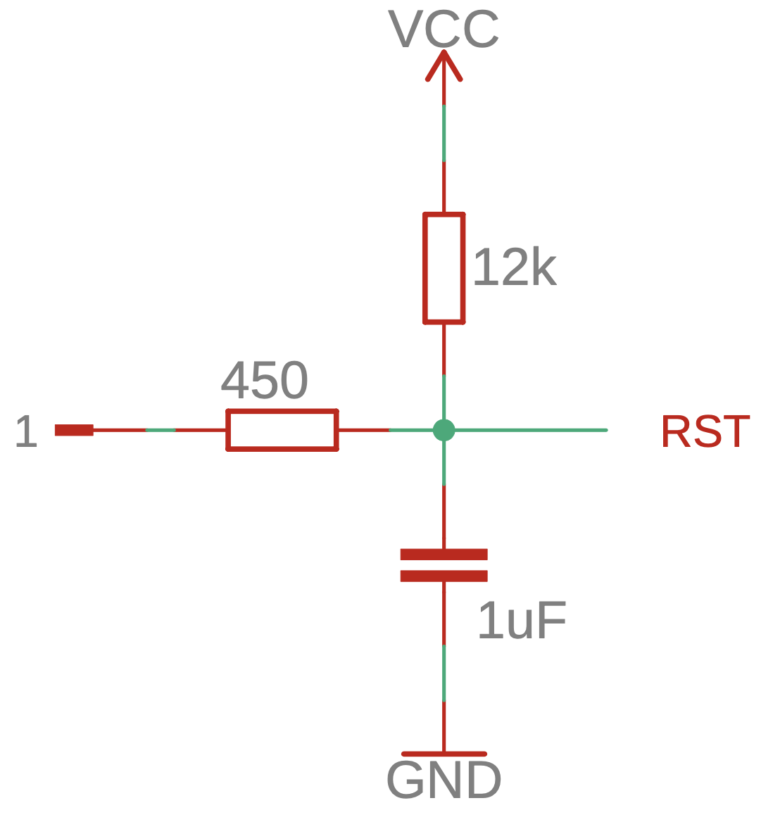
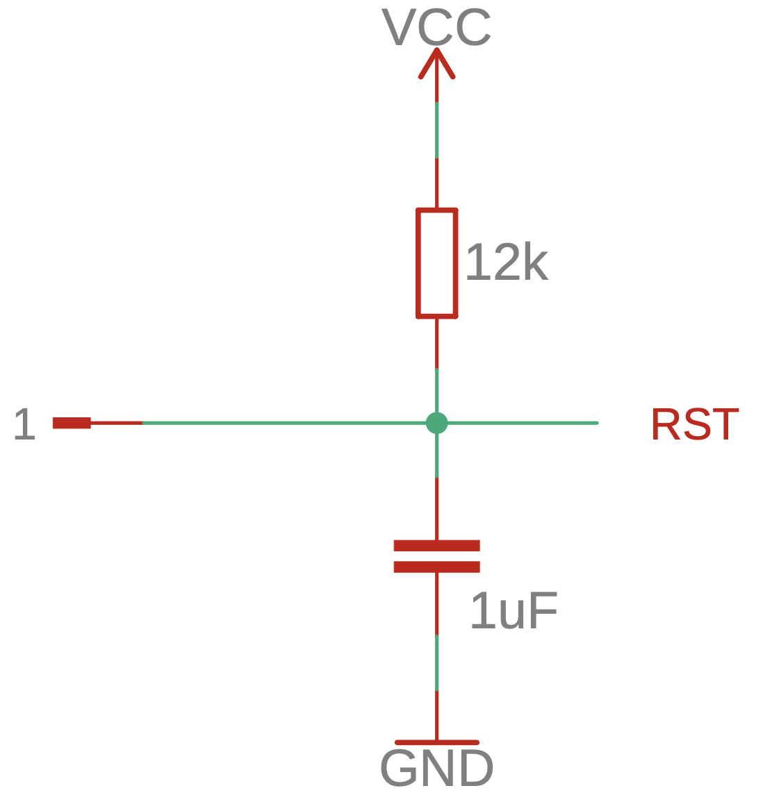
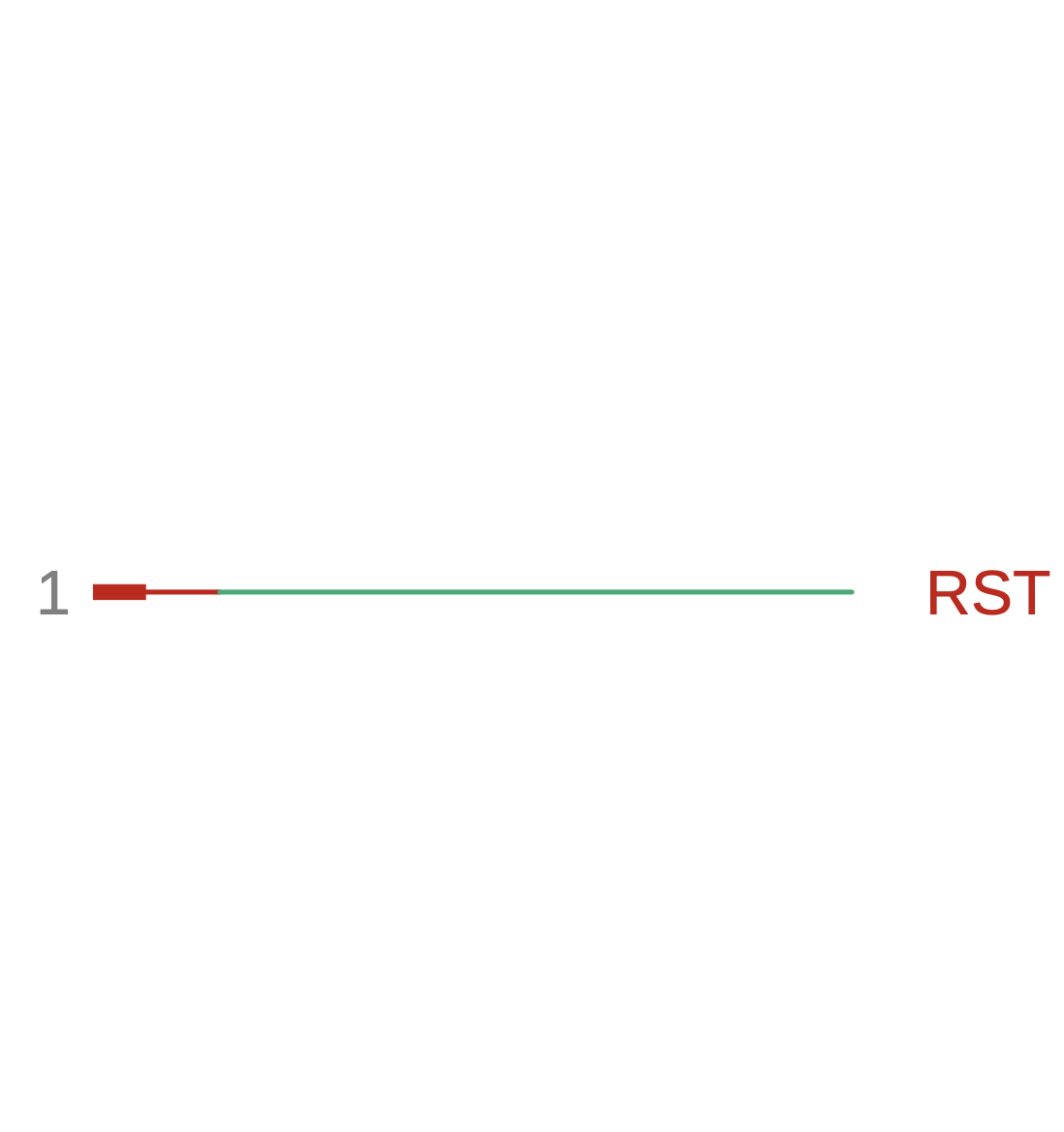
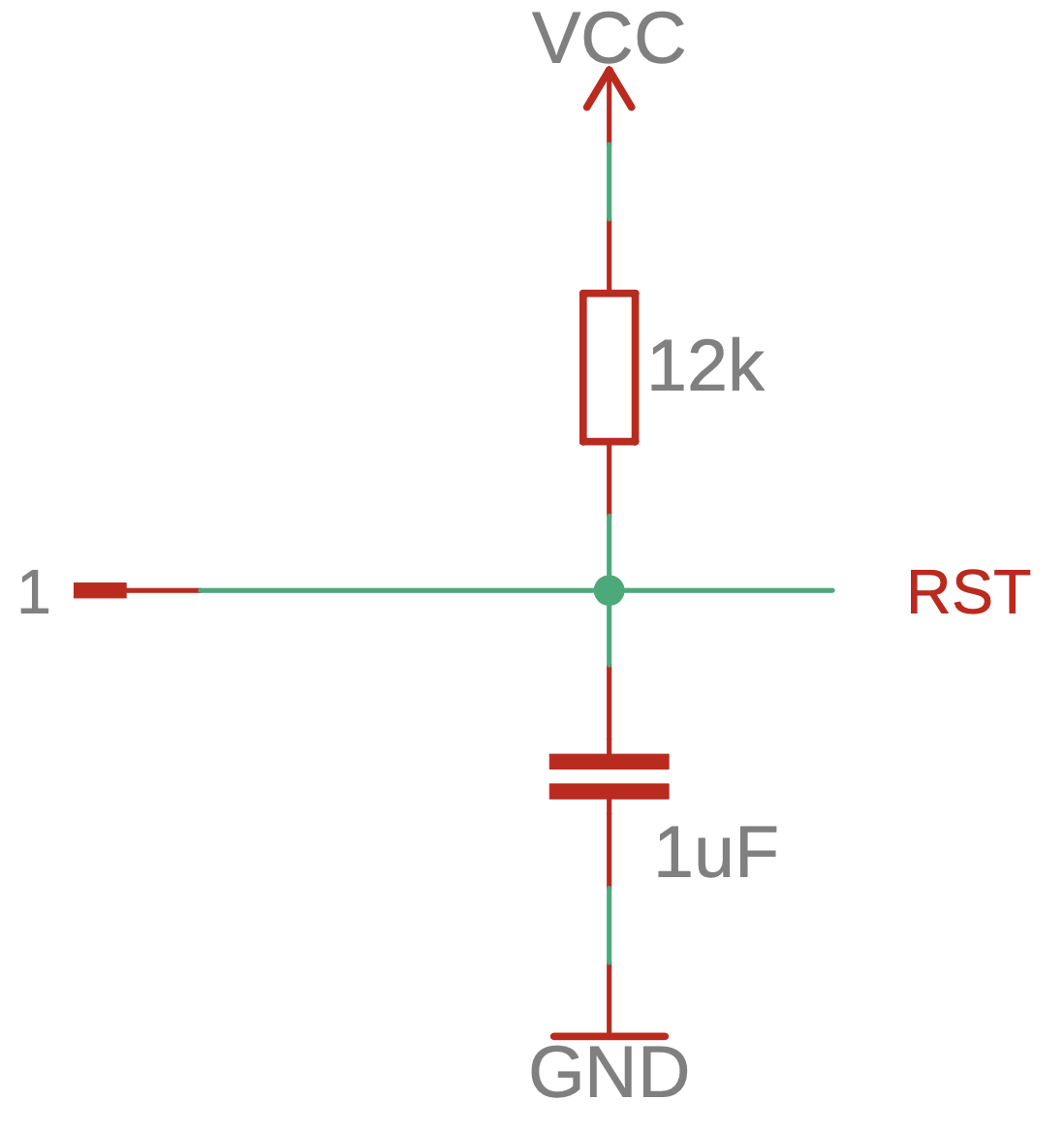
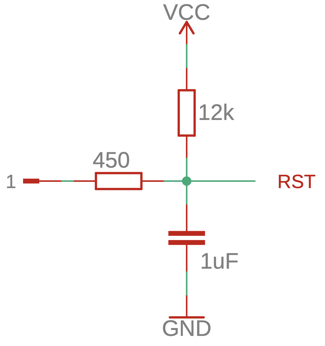
Furthermore, the modules differ slightly in how the reset pin circuit is realized. Figure 2.2 below shows how the module's pin 1 (labeled "1") is connected to the ESP8266's reset pin (labeled "RST").
In contrast to the ESP-01 module, the ESP-07 and ESP-12 modules have additional flash memory and more exposed pins. While the ESP-07 has 16 exposed pins, the ESP-12E and F modules have 22 pins, of which six are unusable.
| Module | Flash memory | LEDs | Other |
|---|---|---|---|
| ESP-07 | 1MB | Power (red), GPIO2 (blue) | Built in ceramic antenna, external antenna can be used (remove capacitor!) |
| ESP-07S | 1MB | no LEDs | requires external antenna |
| ESP-12S | 4MB | GPIO2 (blue) | built in antenna only |
| ESP-12E ESP-12F | 4MB | GPIO2 (blue) | built in antenna only 6 additional, unusable, pins |
Although the minimal circuit required to run the ESP-07 and ESP-12E/F is similar to ESP-01's, the pinout has changed. Pins 1, 3, and 8 need to be connected to VCC, while pin 7 has to be connected to ground. Additionally, pin 16 (gpio15) has to be pulled LOW during boot. Pulling pin 18 (gpio0) low during boot enables the firmware upload mode. Again, a decoupling capacitor is placed close to the microcontroller.
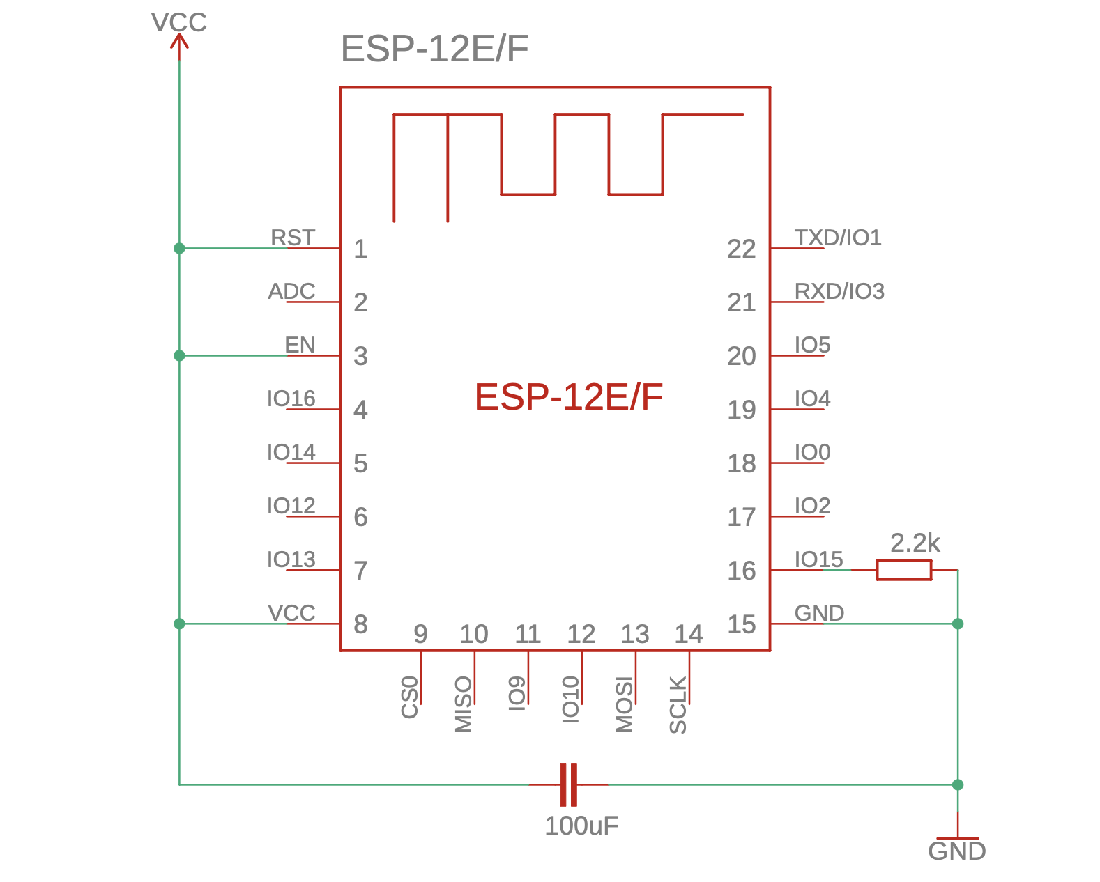
| Pin No. | Name | Description | Behavior on boot |
|---|---|---|---|
| 1 | RESET | low to reset, see Fig. 2.4 | |
| 2 | ADC | analog input, 0-1V | |
| 3 | CHIP_EN | high to enable chip, low to shut down | |
| 4 | GPIO16 | gpio (no PWM), wakeup timer output when using deep sleep | emits high pulse |
| 5 | GPIO14 (SCK) | normal gpio or serial clock (SPI) | pulled high |
| 6 | GPIO12 (MISO) | normal gpio or master input slave output (SPI) | pulled high |
| 7 | GPIO13 (MOSI) | normal gpio or master output slave input (SPI) | pulled high |
| 8 | VCC | +3.3V, uses up to 430mA | pulled high |
| 9 | already used to connect to built-in flash memory | ||
| 10 | |||
| 11 | |||
| 12 | |||
| 13 | |||
| 14 | |||
| 15 | GND | ground | |
| 16 | GPIO15 (CS) | normal gpio or chip select (SPI) | has to be pulled low |
| 17 | GPIO2 (TxD1) | normal gpio, connected to blue LED (illuminate on low) | serial output, not allowed to be low |
| 18 | GPIO0 | low on boot to enter programming mode, high or floating for normal boot | |
| 19 | GPIO4 | normal gpio | |
| 20 | GPIO5 | normal gpio | |
| 21 | GPIO3 (RxD) | Serial input/GPIO | pulled high |
| 22 | GPIO1 (TxD) | serial output or normal gpio | serial output, not allowed to be low |
Furthermore, the modules differ slightly in how the reset pin circuit is realized. Figure 2.2 below shows how the module's pin 1 (labeled "1") is connected to the ESP8266's reset pin (labeled "RST").
Although the ESP8266 is a great chip, it has several drawbacks.
This post is part of a complete ESP8266 reference/guide. You can find more information on how to use your ESP8266 module effectively at blog.hirnschall.net/esp8266/.

The content published on this page (with exceptions) is published under the CC Attribution-NonCommercial 3.0 Unported License. You are free to share on commercial blogs/websites as long as you link to this page and do not sell material found on blog.hirnschall.net/* or products with said material.
1: As an Amazon Associate I earn from qualifying purchases.