Everything you need to add WiFi to Arduino: wiring, code examples, web server, EEPROM, and PCB layout — one reference hub.
blog.hirnschall.net


Today we are going to design and build the best motorized DIY camera slider out there. Including all the bells and whistles like wifi, programmability, and dual moving gantries for an extra compact form factor.
If you are not interested in the design process you can skip to the assembly guide and required parts list here.
As always, let's start with a list of must-have features before designing the required parts:
To capture stunning hyperlapses (moving timelapses), the slider has to have a motor and the ability to control the camera, the number of photos, movement of the camera, etc.
To set all these parameters, we will use a web app on our phone (via wifi).
For me, the goto microcontroller with wifi capability has to be the esp8266 12f module. It is small, cheap, has a lot of memory, and is easy to work with. If it has enough IO and memory it should be a great fit.
A traditional slider can move the camera as far as it is long. However, using two moving gantries (like the edelkrone slider for example), one for the camera and one for the tripod mount, the camera can move almost twice as far as the slider length. Using this design the slider can be much smaller and even fit into a backpack. One downside of this construction is that the tripod mount gantry has to be very stiff to not flex under the weight of the camera (as the slider acts as a lever).
We will use a piece of 70mmx4mm aluminum profile to avoid this problem.
Using an esp8266 we can use the Arduino programming language and the Arduino ide, making this project more accessible. Programming can also be done using an Arduino as described here.
I think it would be nice to be able to add a 3 axis gimbal in the future. The slider should be able to handle the added weight and I also want to control the gimbal via the web app.
However, this is not a top priority feature and might not be feasible.
Since we will have two moving gantries I think it is best to use 2020 v-slot aluminum extrusions. They are cheap and the two gantries can easily be mounted using v-slot rollers.
The number one error I have seen on other slider projects is sag. If the chosen guide rails are too weak the slider is unusable as the camera will not move on a straight line. However, as we will be using short 2020 aluminum extrusions this is not a problem.
If we choose a motor with too little torque, we will not be able to use the slider at an angle. This is one of the mistakes I made last time.
As you can see in fig. 2.1, the torque of a motor is given by \(T=r\cdot F_T\) where r is the length of a lever connected to the motor shaft and \(F_T\) is the force applied. Combined with fig. 2.2 and 2.3 it is easy to see how to calculate the required torque \(T = r\cdot F_T=R\cdot F_A\)
F_T is specified by on the datasheet for your motor and \(F_A\) can be can be calculated using the weight of the slider including your camera \(G\) (\(F_G=G\cdot9.81\)) and
$$F_A=\frac{\cos^{-1}(\varphi)}{F_G}$$
where phi is the max angle you would like to use your slider at.
You can see the connection between \(F_A,F_G\) and \(F_N\) in fig. 2.3. As we are using bearings on the gantry we are not taking friction into account. Instead we will use a motor with a slightly higher torque rating than calculated here. So
$$T>R\cdot F_G.$$
I would like to use a nema 17 pankace stepper motor as they are cheap, readily available and easy to work with. A stepper motor can also be used to position the camera accurately for moving timelapses.
We have already seen how to calculate the required Torque. My camera weighs 480g, the slider 1446g (including the motor) and I would like to use the slider at an angle of up to 90deg. Lets assume a maximum weight of 2kg. Thus I have to choose a motor with at least 0.157Nm of torque. Unfortionately a standard nema 17 pancake motor with 0.13Nm torque is not sufficient. This is because the rated torque is the holding torque of the motor. The actual torque while moving is much lower. Thus the motor might be able to hold the slider in place but it would not be able to move it.
To circumvent this problem we'll use a 40:1 worm gear to drive the belt connecting both gantries. This might be a problem for filming as we reduce the maximum speed the camera can move at by a factor of 40, but as I mainly want to capture hyperlapses this is not a problem for me.
As a generic nema 17 pancake stepper has not enough torque for our purposes, we will use a gearbox to trade rotational speed for torque. For moving timelapses it is probably best to use a worm gear with a \(40:1\) gear ratio. In contrast to e.g. a planetary gearbox, a worm gear cannot be back-driven. Thus the motor can be disabled when the camera is not moving, saving power.
Let's now calculate the torque this system can deliver [1]:
Assuming a machine efficiency \(\eta=0.3\), motor torque \(T_M\) and rotational speed \(\omega_M\) we can calculate the speed (\(\omega_W\)) and torque (\(T_W\)) when using the worm gear as follows:
$$
T_W = \eta\frac{40}{1}T_M = 12T_M
$$
$$
\omega_W = \frac{\omega_M}{40}
$$
As most people already own a power bank, I would like to use one to power the slider if possible. Let's first check if this is a feasible approach.
Let's say the power bank can supply 2.4A at 5V using 1 USB port and 3A when both USB ports are used simultaneously. As we want to use a stepper motor at 12V we will also have to use a boost converter for which we assume an efficiency of about \(75-95\%\). Thus the power bank can supply $$ A^{(1)}_{out}=2.4*5/12*0.75 = 0.75A $$ at \(12V\) using one USB port and $$ A^{(2)}_{out}=3*5/12*0.75 = 0.93A $$ at \(12V\) using both USB ports at once. Using a lab bench power supply we can confirm that the provided power is sufficient to run our motor.
The power bank I am using is rated for \(20000mAh\). This means it has enough capacity to supply \(20A\) for one hour. As we can only draw a current of up to \(2.4A\) from the power bank, it will last for \(8.33\) hours. This should be more than enough for our purposes.
Designing a pcb to fit our needs is not very interesting so here are the results (available on github):
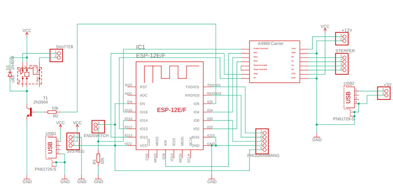
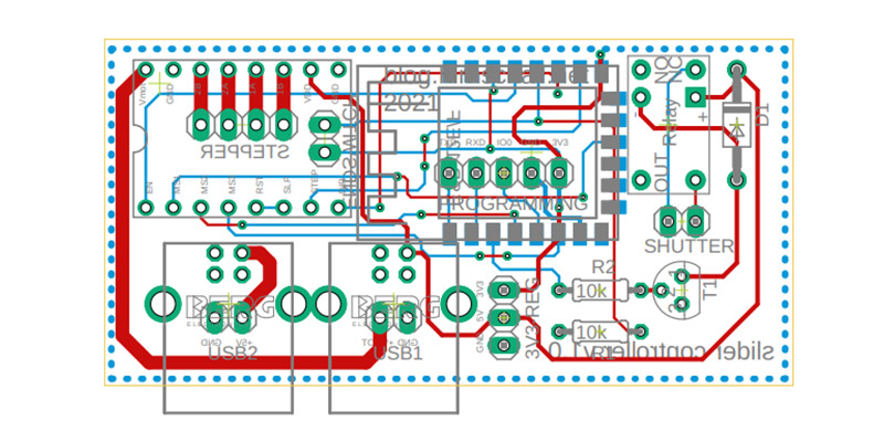
NOTE: add a 16V 1000uF capacitor to the 5V to 12V boost converter. You can also add one to the input.
To make this slider actually usable in day-to-day work, we have to combine 3d printed parts where possible with metal parts where required. This is especially noticable on the outer moving gantry. Here a fully 3d printed part is to flexible and cannot support the weight of the slider with attached dlsr. We therefore have to use a thick 6mm aluminium plate in combination with 3d printed parts to get teh best of both worlds.
All required 3d models are available for free at printables.com with the technical drawings for the metal plate available on GitHub.
To build your own slider you will need the following parts:
As some components cannot be puchased individualy online you can try to buy them at a local electronics reseller. However, as these are all commonly used parts you can also keep them for later projects.
| Component | Quantity | Where to buy |
|---|---|---|
| 3d printed parts set | × 1 | Printables.com |
| Custom PCB | × 1 | |
| esp8266 12F | × 1 | |
| 5V to 3.3V step-down converter | × 1 | |
| 5V to 12V boost converter | × 1 | |
| 16V 1000uF Capacitor | × 2 | |
| a4988 stepper driver | × 1 | |
| 5V relay (Tianbo TR5V M-S-Z 05VDC) | × 1 | |
| 5V transistor (bc337) | × 1 | |
| 10k resistor | × 2 | |
| USB Type-B port | × 2 | |
| 2.5mm 3pin port (pj208) | × 1 | |
| pancake Nema17 stepper motor | × 1 | |
| 40:1 worm gear set (5mm bore) | × 1 |
|
| 5mm×100mm shaft | × 1 | |
| 685ZZ 5x11x5mm bearing | × 2 | |
| micro limit switch (endstop) | × 1 | |
| 2020 V-Slot extrusions (I used 500mm) | × 2 | |
| V-Slot roller | × 12 | |
| m5x25 din912 screw | × 12 | |
| m5 thin nut | × 12 | |
| m5 washer | × 18 | |
| m3x12 din912 screw | × 4 | |
| m3x6 din912 screw | × 14 | |
| m3x8 din912 screw | × 22 | |
| m3 nut | × 4 | |
| m3 t-slot nut | × 16 | |
| m3x5.7 threaded insert | × 8 | |
| gt2 timing belt | × 1 | |
| belt pulley | × 1 | |
| belt idler (5mm bore) | × 1 | |
| #CommissionsEarned | ||
Although not all parts can be purchased individually, we will only consider the cost of components used in this build. Leftover parts can be used in other projects.
All in all, I am very happy with how this project turned out. It is not only much cheaper than commercially available sliders, but it is also so good that I am happy using it over an off-the-shelf slider (even if money was no object). One thing I noticed, however, is that the compact design using two moving gantries requires a very sturdy tripod which is kind of a downside. Of course, the slider would be twice the size otherwise.
Everything you need to add WiFi to Arduino: wiring, code examples, web server, EEPROM, and PCB layout — one reference hub.
Build a multi-switch useless box with a single moving arm, custom PCB, and 3D-printed mounting — full Arduino code and STL files included.

This project (with exceptions) is published under the CC Attribution-ShareAlike 4.0 International License.
1: As an Amazon Associate I earn from qualifying purchases.

