Impedance matching, differential pairs, crosstalk, S-parameter analysis, full wave 3D FEM simulation, and much more.
blog.hirnschall.net


In recent years the ESP8266 has become one of my go-to choices for smart home/IoT devices or projects requiring WiFi. It is cheap (around $1.5 on Amazon)1, has WiFi, and can be programmed using the Arduino IDE, making it an easy replacement for Arduinos if we need WiFi connectivity.
This post outlines the most important guidlines when designing a pcb for an ESP8266 module. It is part of a complete ESP8266 reference you can find here.
Espressif provides a hardware design guide for free. Noticeable takeaways are that we want to place the antenna of the esp module outside of our PCB or, if this is not possible, at least 15mm away from other components (keep-out zone). Meanwhile, [10] only shows a 5mm keep-out zone, as depicted in Fig. 6.1 (c) below. According to [1], we also want to avoid using resistors larger than 2.2k near the esp module as they might be affected by the WiFi. Up to 2.2kOhm seem to work without issues.


This post is part of a complete ESP8266 reference/guide. You can find more information on how to use your ESP8266 module effectively at blog.hirnschall.net/esp8266/.
Below are links1 to the ESP modules and development boards I personally tend to use. If you are unsure about which one to choose, check out this comparison post!
| ESP-12F | NodeMCU ESP8266 | ESP32-WROOM-32 | ESP32-S3 |
|---|---|---|---|
| amazon.com amazon.de |
amazon.com amazon.de |
amazon.com amazon.de |
amazon.com amazon.de |
| #CommissionsEarned | |||
Impedance matching, differential pairs, crosstalk, S-parameter analysis, full wave 3D FEM simulation, and much more.
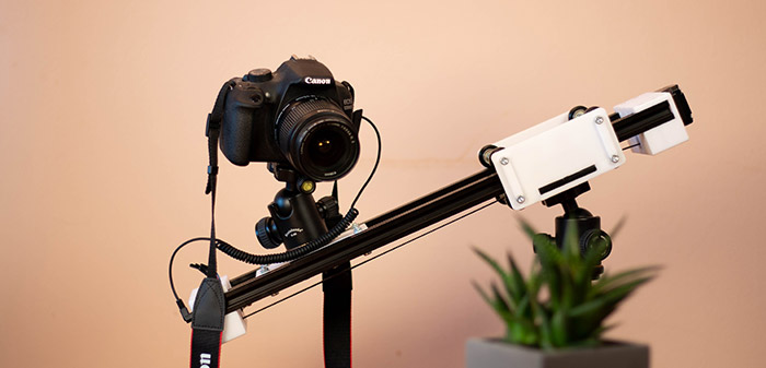
Build a WiFi-controlled DSLR camera slider for under $100 with 3D-printed parts — full BOM, wiring, and control code included.

This project (with exceptions) is published under the CC Attribution-ShareAlike 4.0 International License.
1: As an Amazon Associate I earn from qualifying purchases.