Design a re-entrant auxetic structure, simulate it with FEM, and 3D print it in TPU.
blog.hirnschall.net


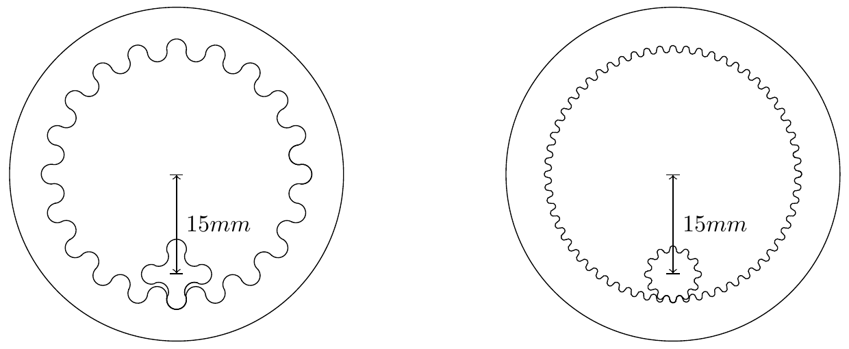
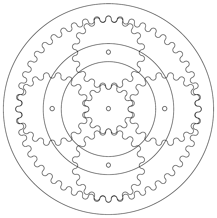
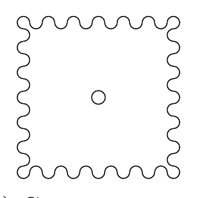
Under normal circumstances, involute gears are the way to go as they offer many advantages when compared to other gear profiles. However, if non-circular gears are required drawing an involute gear profile can become complicated as not all teeth are the same size.
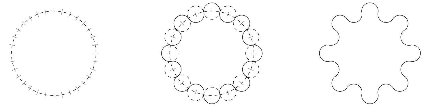
As FDM 3d printed parts are (in general) not as strong as metal parts and therefore torque and transmission efficiency is not as important, we can try to use a different gear profile. If we use circular teeth we ensure that all teeth have the same size regardless of the gear outline.
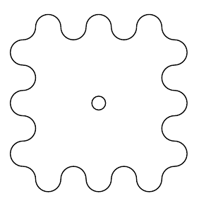
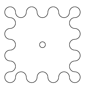
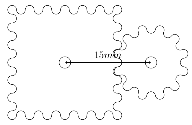
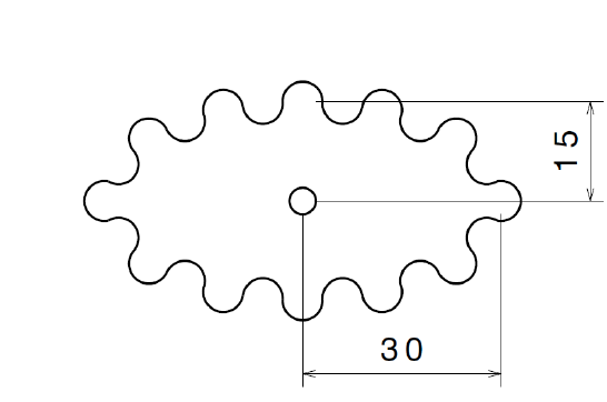
This gear profile is therefore very easy to construct, as you can see in fig. 2 below.
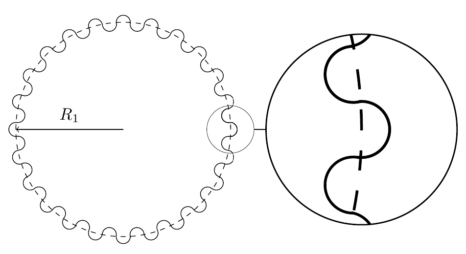
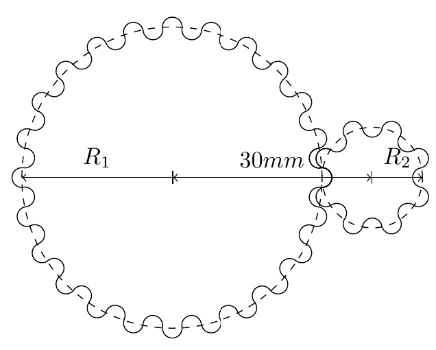
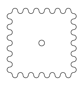
To calculate the required tooth size \(r\) we have to solve a simple system of equations using a computer algebra program like maple for example.
As the required system of equations is dependant on the gear shape, please take a look at the linked PDF paper for more details on how to assemble it.
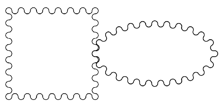
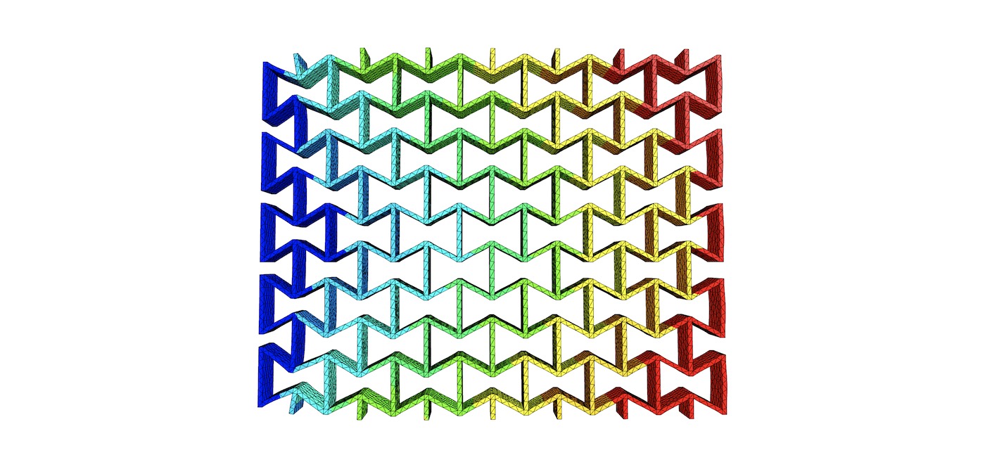
Design a re-entrant auxetic structure, simulate it with FEM, and 3D print it in TPU.
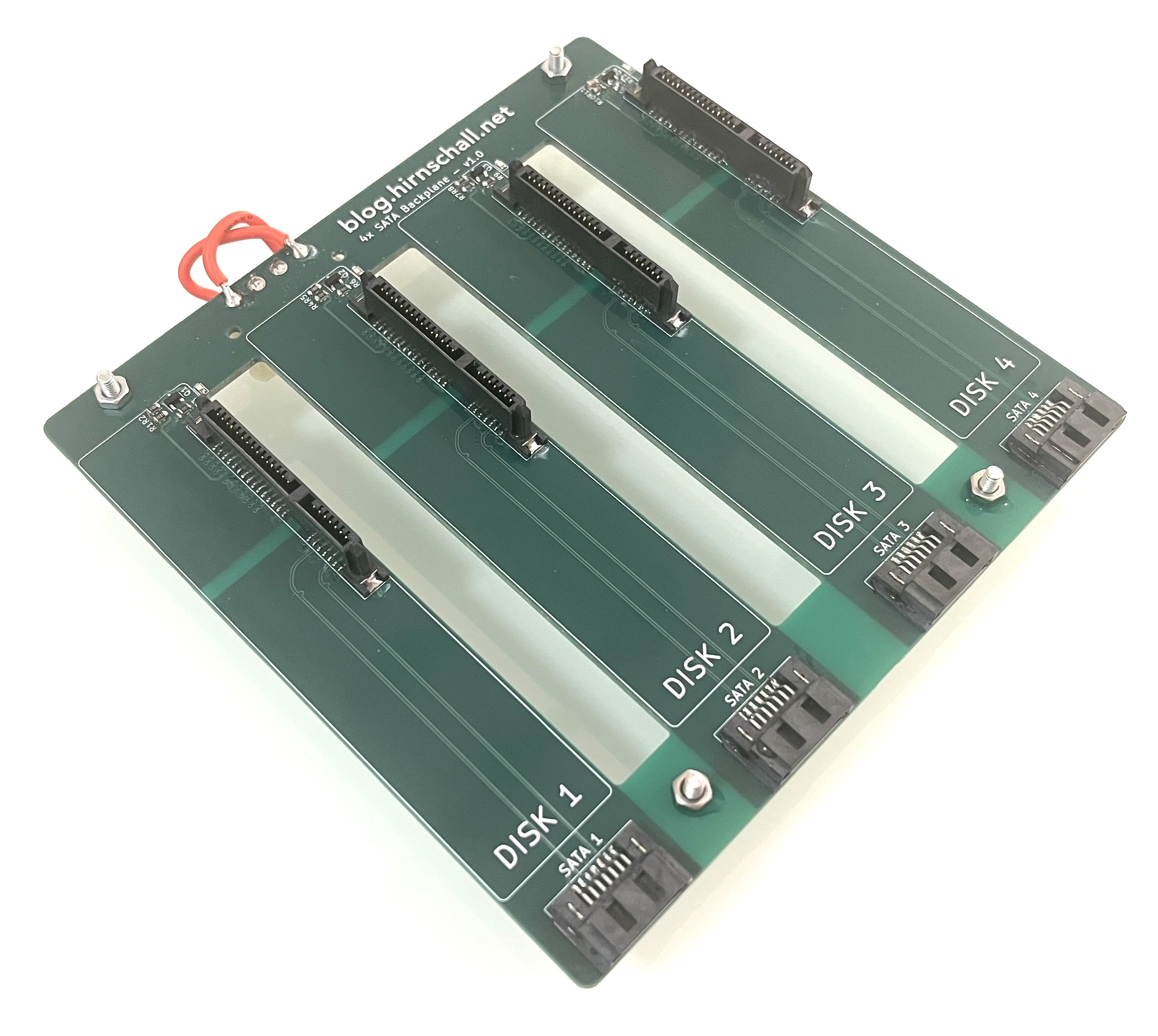
Impedance matching, differential pairs, crosstalk, S-parameter analysis, full wave 3D FEM simulation, and much more.

This project (with exceptions) is published under the CC Attribution-NonCommercial-ShareAlike 4.0 International License.
