Impedance matching, differential pairs, crosstalk, S-parameter analysis, full wave 3D FEM simulation, and much more.
blog.hirnschall.net


Ever since I built my first server and had to sleep in the same room with it, I wanted to build a truly silent home server. And even though the server now lives in the Herrenzimmer (its own room) and noise is not such a big concern anymore, the idea stuck with me ever since.
So, let's build a custom server case that is both quiet and nice looking.
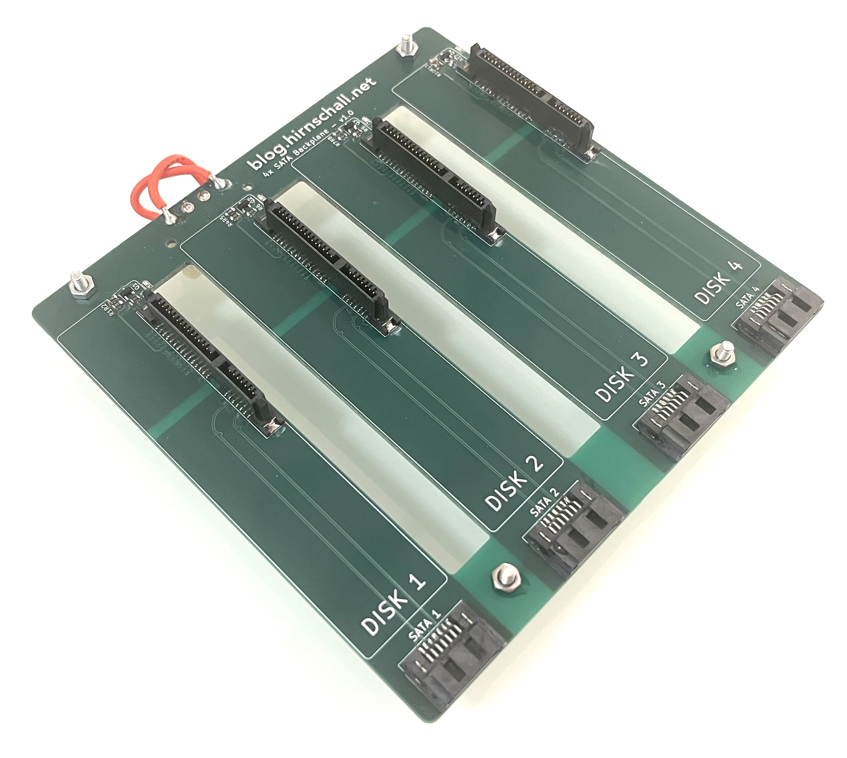
This project concludes the build we started with building a custom 4x backplane.
For this build to be actually useful, I want it to be reproducible along with some other requirements:
As we have already set which backplane we will use (a custom one), we can focus on the case itself. For it to be reproducible, we will choose standard size 1mm thick cut aluminium sheets.
To keep things quiet, we will line the entire interior with 1cm thick automotive sound dampening foam. We will not use common acoustic foam that is normally mounted on walls. It is not suitable for this application.
For cooling, we will build the case to force front to back airflow. The backplanes drive cage supports mounting a 120mm fan. So, from front to back we will have the drives, two fans, the mainboard. We will mount the power supply above the PCIe slots. As long as we choose 1u expansion cards, this will fit nicely. We will orient the PSU with its fan facing the PCIe cards. As PSU fans are typically intake fans, this will help to suck air away from the expansion cards and exhaust it out the back of the case.
The case will be built from six 1mm thick aluminium sheets and four 2020 aluminium extrusions. We will mount the top, bottom, left, and right panel to the slots in the extrusions using t-nuts. To mount the front and back panel we can tap an m6 thread in the ends of the extrusions.
Fig. 1a shows the case and with the mainboard and one backplane installed (test fitting).
To mount the mainboard and backplanes, we will use u profiles (20mm wide and 10mm thick). This way we can place acoustic foam between the outer panel and the u profiles (more on the foam later). The mainboard will sit on m3 brass standoffs. The backplanes will be mounted using m3 rubber isolation standoffs. This way we isolate any vibrations coming from the drives from the case itself.
Another nice bonus is that we can slide the profiles in and out as they slide into the extrusion's slots. One such rail with rubber standoffs mounted is shown in fig. 1b below.


Fig. 2 shows the connected backplanes with attached fans and how the profiles supporting them slide out as a whole subassembly.

Like a rack server, we will push air through the case from front to back. To do so, we add a 3D printed bracket between the front panel and the case. We do the same on the back. This will allow enough air to enter and exit the case without the need for high static pressure (and high noise) fans. To prevent air recirculation inside the case we can add a simple cardboard wall around the fans (splitting the case in a front and back part).
The 3D-printed air inlet/outlet is shown in fig. 3 below.
If we choose the top and side panels 4cm longer than the bottom one, we can cover the bracket. Air will then enter through the bottom.
For fans, we went with the new Noctua NF-A12x25 G2 120mm fans or the older, slightly cheaper, NF-P12 redux as an alternative. Either way, any 120mm fan will fit. The Noctua ones are quiet and have good static pressure. We will use two of them, one for each backplane. Mounting them between the motherboard and the backplanes gives a clean separation between the front intake and the rear exhaust.
To make the case silent we will try to block the three main ways of sound transmission:
We use soft rubber standoffs to mechanically decouple the backplanes from the case. This way vibrations from both the drives and fans are isolated and do not transmit to the case and into the room.
To block noise coming from the drives and fans we will line the inside of the case completely with 1cm thick automotive sound dampening foam.
We do not want to treat a room, we want to treat a surface. We therefore do not want to use acoustic foam panels that are typically used for wall mounting in rooms. While the wall mounted foam is open cell, the automotive sound dampening foam is closed cell and much heavier. The closed cell automotive foam is the correct choice to stop sound from transmitting through a panel due to its mass and viscoelastic damping properties.
For this build we do not add a second rigid layer to the inside of the foam although it would probably improve the acoustic performance quite a bit (constrained layer damping - CLD).
This one is the hardest to get right. Noise will transmit through any opening in the case. Unfortunately we cannot seal the box completely as airflow is required for cooling. What we will do instead is use the 3d printed spacers and the acoustic foam to remove any line of sight from the outside to the noise emitting components.
The 3D printed spacers create an offset gap so sound has to turn a corner to exit and that corner is lined with acoustic foam.
If this is still not enough, we can add a "sound maze" (fig. 4) to further reduce noise transmission. As this will also affect the cooling however, we will try it without the maze first.

For my setup, using an mATX motherboard, I used panels and extrusions of the following size (fig. 5):

Panels of this size will leave the 3d printed spacers visible. If you want to hide them you can add 4cm (2cm per spacer) to the length of the top panel. So the panel ends up as 35cm x 44cm.
You can also do so for the side panels. However, it will cover the air inlets on the side. This is probably ok for most setups as the bottom is still open.
To accurately cut the PSU opening, we will use a template. To do so we first stick painters tape to the actual psu. We can then trim the edges and transfer the tape to the panel we want to cut. We can then fine tune where we want to cut on the inside. You can see the tape on the PSU and the final template on the actual aluminium sheet in fig. 6.


To make this case really stand out, we can add nice aluminium feet like on old HiFi systems. The ones I used also have a nice rubber bottom, further helping to reduce vibrations and noise.
The feet are 40mmx20mm and simply screw into the bottom sheet metal panel using a nut and a bolt. I offset mine from the edge by about 1cm so that the nut on the inside does not interfere with the 2020 extrusions.
Below is a list of all non standard components used in this build. Things like extrusions or aluminium sheets are best sourced locally to avoid shipping costs.
| Component | Quantity | Where to buy |
|---|---|---|
| m3 rubber standoffs | × 8 | amazon.com amazon.de |
| Acoustic dampening foam | × 1 | amazon.com amazon.de |
| HiFi Feet | × 4 | amazon.com amazon.de |
| Sata Backplane | × 2 | Blog Article GitHub |
| #CommissionsEarned | ||
Note on quantities: The quantity listed is the actual number of pieces needed. If you need e.g. four feet, and the amazon listing is for a pack of four, you only need to order one pack.
Overall, I am extremely happy with how the case turned out. It looks nice, and the build process was easier than expected. Going into the details of sound transmission was quite interesting as well.
At the time of writing, the 3D printed spacers are not yet fitted, so a final acoustic verdict is still pending. That said, the previous iteration of this build, with larger openings and the wrong foam type, was already almost inaudible in normal use. With proper automotive damping foam lining every panel, rubber-isolated drive mounts, and no line of sight from the outside to the noise sources, this version should perform at least on par and likely better.
If it is not quiet enough, adding a sound maze to the air inlets and outlets or bonding a second rigid layer on top of the foam (constrained layer damping, CLD) are the logical next steps.
Impedance matching, differential pairs, crosstalk, S-parameter analysis, full wave 3D FEM simulation, and much more.

Eliminate manual bit packing errors with compile-time validation and code generation — full C++ implementation included.

This project (with exceptions) is published under the CC Attribution-ShareAlike 4.0 International License.
1: As an Amazon Associate I earn from qualifying purchases.
