Everything you need to add WiFi to Arduino: wiring, code examples, web server, EEPROM, and PCB layout — one reference hub.
blog.hirnschall.net


Although a useless box might be pretty useless, I like the concept of a robot with multiple switches whose whole job is to "undo" every switch you flip.
I also want to build this project as a gift for someone I am sure will enjoy it.
As this project is quite simple, there are not many design considerations. We can use many of the DIY motorized Slider project concepts.
There are many useless box kits available for purchase online. However, most of them only have one switch or have one arm per switch if they have more than one. We will use multiple switches and a single moving arm to flip the switches back off to make this project more sophisticated and more enjoyable.
As the box will be pretty small, I think we can get away with using a (usually quite expensive) linear guide rail and a stepper/timing-belt set up to move the arm from switch to switch.
To move the arm that pushes the switches, we will use a small 9g servo. Doing so might not be the best idea as the switches I use are hard to press, and the servos are relatively weak. However, they are small and easy to work with.
Most useless boxes I have seen online use the extending arm to open the lid. However, I have also seen some DIY useless boxes that use a second servo to open the box cover, resulting in a much more sophisticated operating mechanism. Especially once the arm starts moving between switches without fully retracting. If we have a spare PWM pin available, this should be easy to implement using a second 9g servo.
As this project requires no special features, we will use the "standard" ATMega 328p chip. It is cheap, has enough IO pins, comes in an easy-to-solder DIP28 package, and as it is also used in the Arduino UNO boards, this project will be Arduino compatible, making it much more accessible to novice makers. We will also use an extra Arduino board as ICSP to program the chip once everything is assembled.
We will use a standard a4988 stepper driver module used in most cheap 3d printers in combination with this stepper library to easily control the pancake stepper motor with our ATMega chip.
Both the stepper motor and the servos we use make noise once powered on, so we will detach the servos and disable the stepper motor 30 seconds after the last button is pressed.
As (unfortunately) the wooden box is not perfect, we have to glue the 3d printed parts together such that the printed part touches not only the bottom of the box but also both sides—this way, the plastic parts can be mounted securely.
Note: try to buy components like a single resitor or capacitor locally as they can be rather expensive and only available in large quantities online.
We will use the following parts to assemble one box:
| Component | Quantity | Where to buy |
|---|---|---|
| 3d printed parts set | × 1 | Prusaprinters.org |
| PCB (optional) | × 1 | |
| ATMega 328p | × 1 | |
| A4988 module | × 1 | |
| Nema 17 pancake stepper motor | × 1 | |
| MGN12H linear rail | × 1 | |
| 9g Servo | × 2 | |
| 12V DC power supply | × 1 | |
| 12V to 5V DC converter | × 1 | |
| 10k resistor | × 1 | |
| 22pF or 20pF capacitor | × 2 | |
| 100nF capacitor (optional) | × 1 |
|
| 47μF capacitor (optional) | × 1 | |
| 16MHz oscillator | × 1 | |
| switches | × 6 | |
| endstop | × 1 | |
| female-female jumper wires | × 1 | |
| male pin headers | × 1 | |
| Belt and pulley set | × 1 | |
| Idler pulley | × 1 | |
| Bearing 684ZZ (4x9x4mm) | × 1 | |
| Box (21.5x13.8x10cm) | × 1 | |
| #CommissionsEarned | ||
Note: the box you use should not be smaller than 21.5x13.8x10cm (length,depth,height). If the box you use is wider of deeper than this, there is no problem. If your box is higher, you can use a 3d printed adapter or some pieces of wood as a spacer to fix the rail mount at the correct height.
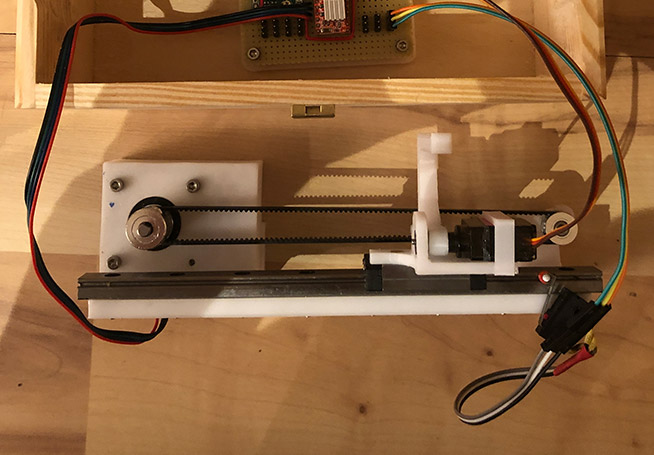
We will start with the motion system. Both the motor mount and the pulley mount have to be glued to the main rail mount. This ensures that the 3d printed part fits perfectly inside the box, touching the bottom and both sides of the box.
An easy way to glue the parts together:
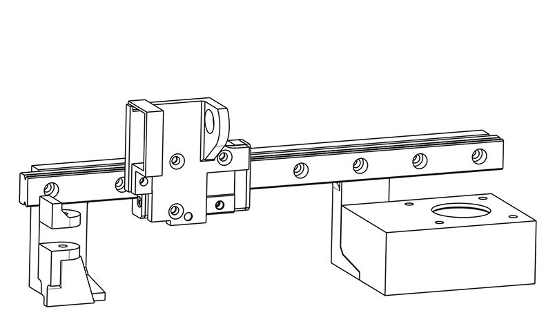
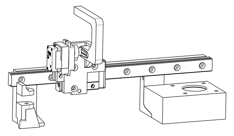
Next, assemble the moving gantry as seen in the two images (fig. 1.1 and 1.2) below. Mount the servos after the calibration step!
Note: The servo is not made to hold the forces applied to the moving arm when a button is pressed. Thus we need to insert a small 684ZZ bearing into the rail-block-mount.stl part. Furthermore, to strengthen the connection between the arm and the bearing, we will drill a small 1-2mm hole in the arm (where the arm is inserted into the bearing) and insert a metal pin (use an m2 screw, a dowel pin, or a nail).
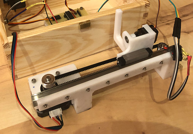
As this project is a present for a friend, I used a prototype board instead of a professional PCB to solder the circuit. However, I have designed a PCB you can order online to simplify the soldering process. Use the schematic down below to assemble your PCB.
Once the PCB is assembled, you can use the programming header and Arduino as ICSP to program the board.


Flash the calibration.ino file using the Arduino ide.
Once you connect the motor, both servos, and the 12V DC jack to your PCB, the calibration process begins.
Once powered on:
Once everything is set up and works outside the box, it is time to glue the printed parts inside the box using epoxy resin. We will use glue to avoid visible screws from the outside.
All in all, I am pleased with how this project turned out, although I dislike the idea of gluing parts together without a straightforward way to line them up correctly.
Once the motors turn off, the box is completely silent and can stay powered on while on my desk. In my experience so far, it is a great piece to show off, as even non-tech-enthusiasts are curious what the switches are for and like playing with the box.
Everything you need to add WiFi to Arduino: wiring, code examples, web server, EEPROM, and PCB layout — one reference hub.
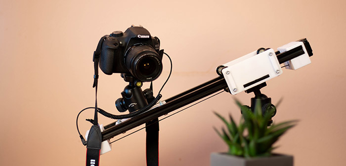
Build a WiFi-controlled DSLR camera slider for under $100 with 3D-printed parts — full BOM, wiring, and control code included.

This project (with exceptions) is published under the CC Attribution-ShareAlike 4.0 International License.
1: As an Amazon Associate I earn from qualifying purchases.


